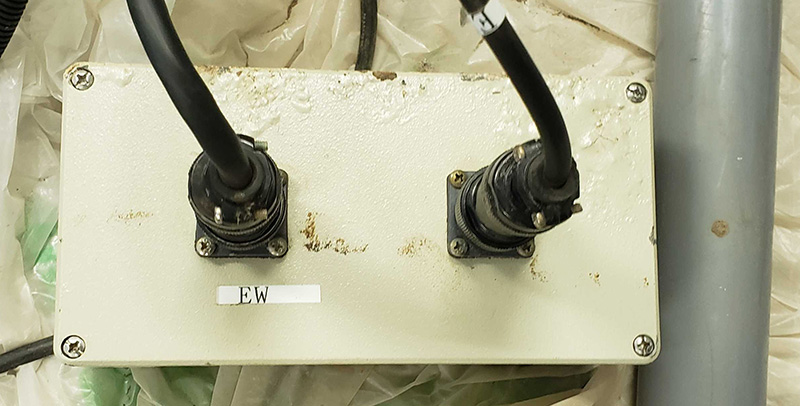
The 1st magnetometer (cr1) was placed in N-S direction at Kawatabi or Onagawa,
and the 2nd one was set in E-W direction at Kawatabi, or N-S direction other than Kawatabi station.
1台目(cr1は)NS(南北)成分用に使用、
2台目(cr2)はEW(東西)成分、または川渡以外の場所でのNS成分観測に使用しました。
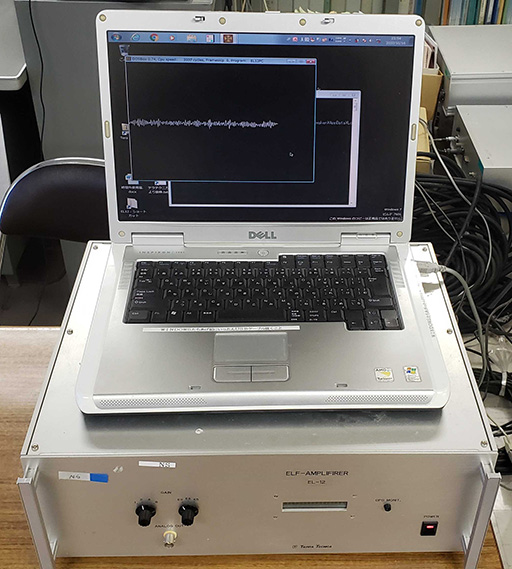
The EL-12 magnetometers detect the magnetic field variations in the frequency range from 0.1 Hz to 40 Hz.
The sampling frequency is 128 Hz.
EL-12は周期10秒から40Hzの範囲の磁場変化を計測するインダクション型磁力計です。
サンプリングは128Hz、16bitです。
The timing of sampling is given by the time information obtained by a GPS antenna
with an accuracy of +/-2microsec with respect to Universal Time.
GPSアンテナを使用して、UT(世界時刻)に対する精度が±2μ秒の時刻情報をサンプリングのタイミングに使用しています。
The digital data were recorded on a magneto-optical disk. Later it was changed to a hard-disk.
デジタルデータは当初はMOディスクに記録、後にハードディスクに記録されるように変更されました。
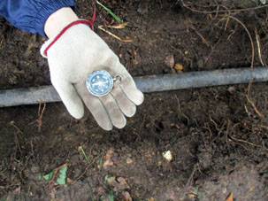
コアにパーマロイを使用した巻き数3万回のインダクションセンサーです。
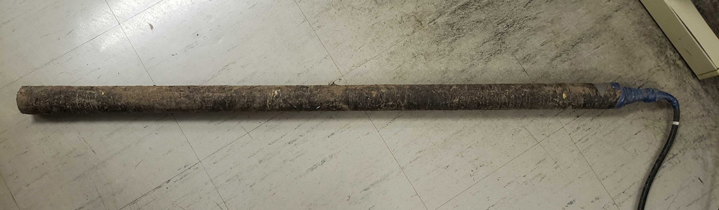
センサーからの信号を1000倍に増幅し、100mのケーブルを通して本体に供給します。
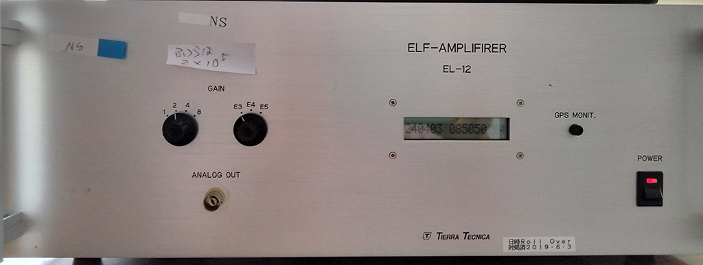
front
back
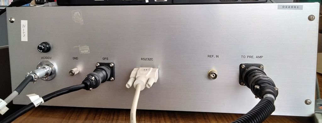
The gain is variable (1,2,4,8) times (1000,10000,100000).
ゲインは1段目が1,2,4,8倍で、2段目が1000,10000,100000倍の可変です。
Adapted from the instructon manual of EL-12, Tierra Technica Ltd., 1997 (in Japanese)
有限会社テラテクニカ社,インダクション型磁力計 EL-12 取扱説明書,1997年-より抜粋。
The figure shows the frequency response of the two magnetometers measured by
Ishikawa and Imai (1998), and Hataoka (2000).
2台の磁力計の感度特性は石川・今井(1998)、および 畑岡(2000)が計測した感度特性のグラフです。
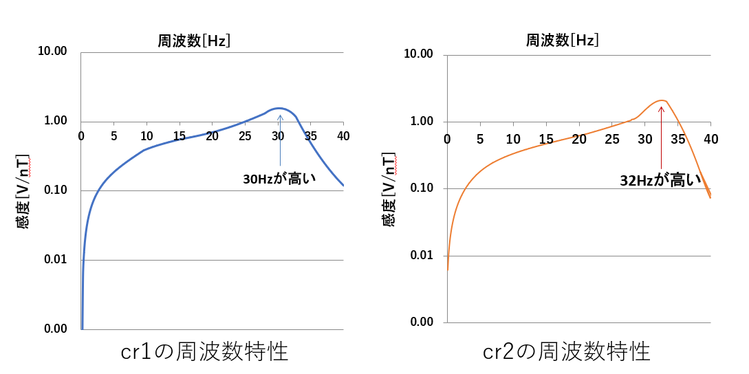
table of frequency response (cr1) for 8s DFT /
table of frequency response (cr2, 2000-) for 8s DFT
The 1st magnetometer (cr1) has a peak at 30 Hz. The peak of the 2nd magnetometer (cr2) is at around 32 Hz.
周波数特性はcr1の感度ピークが30Hz付近で(石川,今井,1998年より)、cr2の感度ピークは32Hz付近です(畑岡,2000年より)。
Ishikawa, Y., and Y. Imai, On calibration of the magnetometers, Graduate thesis, Watanabe Lab.,
Department of Communication Engineering, Tohoku Institute of Technology, 1998. (in Japanese)
Hataoka, H., Frequency analysis of N-S and E-W conponents of magnetic field variations in ELF range at Kawatabi,
Graduate thesis, Nakagawa Lab.,
Department of Communication Engineering, Tohoku Institute of Technology, 2000. (in Japanese)
石川嘉洋,今井 芳春, 磁力計のcalibration,東北工業大学通信工学科 渡辺研究室卒業論文,1998年
畑岡 尚,川渡におけるELF帯地球磁場の南北、東西成分の周波数解析,東北工業大学通信工学科 中川研究室卒業論文,2000年
1999.12.18 Initially the gain was set to be 1x10⁵ / 本体のゲイン1x10⁵で観測開始
2000.06.16 Accidental disconnection of main cable of cr2 / cr2断線、
2000.07.11 Repair the cable: frequency responce changed / cr2ケーブル半田付(感度特性が変わった)
2002.04.30 Accidental disconnection of main cable of cr2 (animal bites) / cr2断線、
2002.07.02 Repair the cablecr2 / cr2ケーブル交換
2012.06.29 The gain was changed to be 2x10⁴ to prevent saturation / 本体のゲインを10万倍から2万倍に変更
2012.11.07 The 150 m main cable of cr1 was replaced with 50 m / cr1メインケーブル 50m に交換
2012.11.07 The 50 m main cable of cr2 was replaced with 100 m / cr2メインケーブル100m 交換
2019. 6.28 The 50 m main cable of cr1 was replaced with 80 m / cr1メインケーブル 80m (slit tube有)に交換
The length of main cable of cr1:
150m 1998-2012
50m 2012-2019
80m 2019-2020
cr1:本体とプリアンプを接続しているメインケーブルの長さは
1998年から 2012年までは 150m,2012 年以降 50m,2019年以降は 80m である。
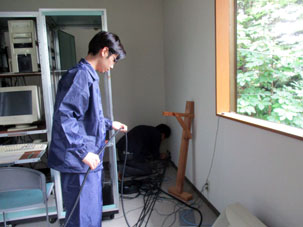
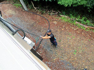
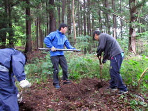
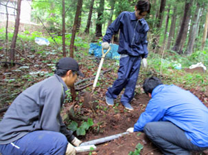
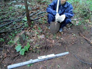
Onagawa, June 28, 2019
2019年6月28日女川で磁力計再設置時の写真: 本体からケーブルを伸ばしセンサーを埋めています。